Try it
R and C in series - Vout is read across C, so lows pass and highs get shorted to ground
Understand the result
What's going on
A low pass filter is a high pass filter’s mirror image: low frequencies pass through mostly untouched, and anything above the cutoff gets progressively weaker. It’s the circuit behind smoothing out a jittery sensor reading or knocking the buzz out of a PWM signal before it reaches an amplifier.
The formula
fc = 1 / (2π × R × C)
Identical formula to the high pass filter - only the output tap point differs.
Show the derivation, mnemonic, and worked example
Build it up
Same resistor and capacitor in series as a high pass filter - the only change is which component you read the output across. Take it across the capacitor instead of the resistor, and the behavior flips: at low frequency the capacitor’s reactance is high, so it happily passes the voltage through to the output; at high frequency its reactance drops, and it starts shorting the signal to ground instead of letting it reach the output.
Worked example
Worked example
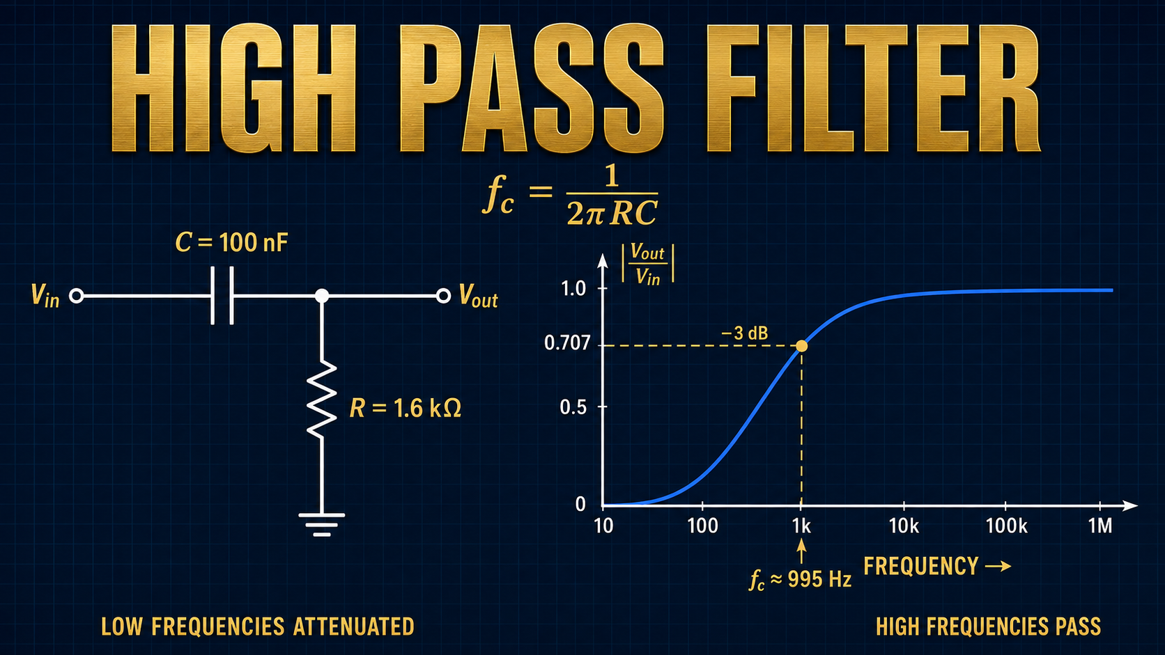
R = 1.6 kΩ, C = 100 nF
fc = 1 / (2π × 1,600 × 1e-7)
fc ≈ 995 Hz